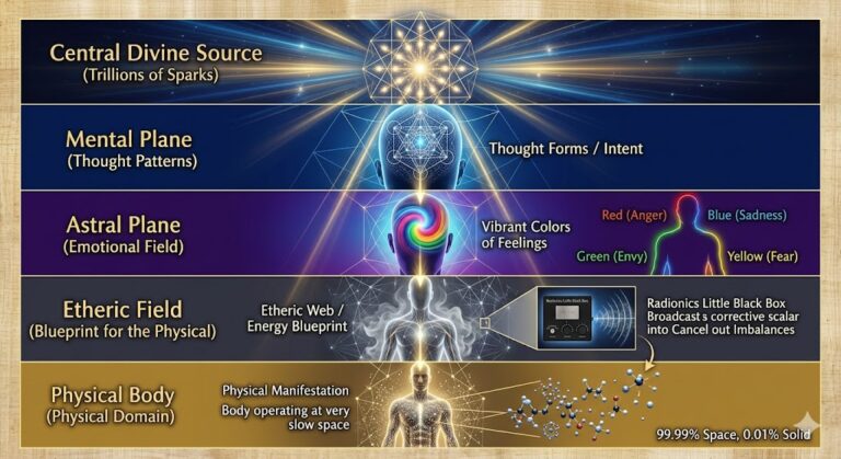
Tag: Radionics

  • About Orgone & Radionics

    About Orgone & Radionics


    About Orgone & RadionicsÐ


    Orgone fields can carry information in the form of wave patterns. Bioenergy and magnetism are only slightly different forms of the same Aether. Aether is a cosmic omnipresent energy that is successively split down into a spectrum throughout material existence. Different ranges in the spectrum derived form Aether are manifest as matter and the electromagnetic spectrum. Bioenergy is part of the Electromagnetic spectrum. Bioenergy and the magnetic field generated by electrical current are close to each other in the spectrum and closely mutually influence each other. My research has led me to believe that Bioenergy is more magnetic than electrical in its nature and may indeed be simply a true form of what we partially conceive of as magnetism. Magnetic fields can carry information, radio waves are an example of this. When a wave carries information through a magnetic field it is called a radio transmission. When a wave carries information through a Bioenergy field it is called radionic data.

    Devices which both generate bioenergy and emit bioenergy wave patterns can be thought of as transmitting antennas, and the wave pattern is the signal to be transmitted. Imagine that the Bioenergy wave pattern (radionic data) produced by a certain element from the periodic table is used as a signal and transmitted. To varying degree, the presence of that element appears to be “simulated” in the area covered by the effect.  I theorize that a subtle projected image of an atom is produced which can, under correct circumstances, behave at least partially like a real atom in a chemical process. In fact, if you have ever heard of quantum physics then you would probably say that’s exactly what an atom is anyway.

    With further research into this aetherochemical effect, it is possible that many industrial dependencies on pharmaceuticals or petrochemicals could be reduced or eliminated. The potential industrial applications for this technology are virtually unlimited. Every day around the world a growing ever-growing number of people use radionics + homeopathy + alternative energy methods for healing and other purposes. With the advent of Orgone Matrix Material, Radionics machines  became much more powerful.

    The designs on this page are simple, easy-to-put together from readily available materials, and well within the range of any tinkers’ skills.  Radionics information is below. Please feel free to copy these pictures to your hard drive if you find them useful. I hope that these schematics will demystify some of the simpler aspects of a radionics machine for you do-it-yourselfers out there who want to make their own, or for those of you simply curious about how it works.

    In simple terms, this kind of orgone radionics machine is basically a closed loop circuit, which you tune by adjusting the dials. It may not make sense from a conventional electronics standpoint, but  that is because it is a radionic circuit and not an electronic circuit. When you put a sample into the witness well, you are introducing interference into that circuit. When you adjust the dials so that the circuit is resonant to a component of the interference you have introduced, then you are ‘tuned in’ to that sample. This state of resonance with the sample produces a change in the way that the EM fields of the machine and your body interact, causing the ‘stick’ where your fingers stick to the pad. With a bit of practice, anyone can use a stick pad. Alternately, you could use a pendulum over the stick pad and dowse to determine when the dials are adjusted correctly for a given purpose.

    About the ‘dials’ used to make radionics machines: it is not necessary that they be calibrated dials, any variable resistor will work. They (variable resistors) are called potentiometers. I have successfully used dials ranging in size from tiny little PCB mount tuning pots up to your average volume dial for a home stereo. I also use slide controls. Larger dials like those used for volume controls on audio equipment are more durable than PCB mount pots, but either will work.

    Any potentiometer will work. It matters that you have variable resistance. A potentiometer is just a variable resistor. They do not have to be calibrated dials. However, the number combinations that you wind up  with (on the dials) will be unique to your machine. Keep notes on the rates for various samples. They will always be the same on your machine, but they will not be the same number combination on two machines, unless the two machines are identical in componentry, right down to the length of wires used to connect the parts and pieces together.

    Many potentiometers have 3 leads in the footprint.  These are the kind I have shown here. Often, the center lead is the output, and for that reason I have drawn the circuits here with the center lead shown as the output. When you get your dials, it is a good idea to check and make sure that you know which terminal is the output, and proceed accordingly. The easiest way to do this is to test with a multimeter and check the resistance between 2 different leads at a time. Test left – cent, right – center, and left – right. Turn the dial as you test the resistance and see if it changes. You will find that two of the leads have either no resistance or a fixed resistance between them, while one of the leads has variable resistance that changes when you adjust the dial or slide on the potentiometer. The one that changes is the one that I am calling the ‘output’ on this page, and I have shown it to be the center lead in these schematics. Of the remaining two leads, it doesn’t matter if they are as shown in the pic below or inverted.

    A potentiometer of this type is designed to run a supply current across two of the leads (that’s what the two outside terminals do) and allow a variable amount of that current to pass through to  the center terminal. Either linear or logarithmic will work.

    As for the resistance value of the potentiometers,  I do not see that it matters a great deal at the simplest level of application. I have used many different resistor values for this kind of a circuit, between 100 ohms 1 Mega Ohm max resistance ought to work. I recommend for simplicity 0 -20K or 0-50K pots. You shouldn’t have too much trouble finding dials, as they are fairly common, and easily salvaged from old electronics, or bought from an electronics supply store.

    Simple 3 Dial

    This diagram shows a basic, easy-to-make radionics tuner. This circuit includes a witness well and a stick pad. In circuits like this I often use a 3.5mm  2-conductor audio jack to connect to the mobius coil output. You could alternately connect the output from this circuit directly to your mobius coil, and leave the jack out. Solder or crimp the connections marked with a dot.

    The stick pad is made from a simple piece of copper flashing, covered by a layer of plastic. Use plastic tape or thin plastic sheet. To use it, you gently rub it with the fingers or thumb of one hand while adjusting the dials with the other hand. When you get the dial ‘tuned in’ you will feel a different sensation in the fingers which are touching the pad.

    For the witness well you can use either a simple piece of sheet metal as above but with no plastic covering for the witness well, or a small metal can, cup or bowl. Copper pipe end caps work well.

    If you want a more advanced and powerful output for this circuit that employs Orgone Matrix Material, you can Make an Orgone Field Pulsar  or check out the  Ring Generator.

    Simple 9 Dial

    The circuit below is a bit more complex, it incorporates 3 mobius coils around a common quartz core. In very simple terms, the output is a 3 channel scalar interferometer. 2 channels are used to modulate information and 1 channel (center) is used as a carrier. The diagram should also give you an idea of how to mount the mobius on the crystal. If you are making the simple circuit above, you can just use one mobius coil instead of the 3 shown below.

    Top of the circuits is a ‘target’ circuit. This decides where to send the energy. It is the one with 3 dials, and it drives the uppermost mobius coil on the xtal. The coil is in the outgoing stream of energy.

     Next is a basic zapper circuit, a square wave generator. The zapper circuit drives the center mobius on the xtal. The coil is at the center of the energy field in & around the xtal. The center coil can be enclosed in a grounded shroud as shown, or a small ORAC. The shroud is an optional improvement. The circuit will work without it. It acts to reduce the EM emissions of the center coil so that the two tuning coils are influenced more by scalar / radionic data and less by the EM carrier signal.

     The ground ballast is a cylinder of HD orgonite inside of a short length of copper pipe. The ground ballast is an optional improvement, the circuit will work without it. It recovers some of the EM energy and converts it into Bioenergy which is injected back into the circuit. If you omit the ground ballast then connect the ground wire from the center coil shroud to the negative lead of the zapper output.

    The Lower coil is connected to the ‘trend’ tuning circuit. This circuit decides what kind of energy it is that you are sending. The coil is positioned on the incoming stream of energy. The trend has 6 dials for finer tuning, and the target has 3 which imo is more than enough for accuracy.

    The Crystal for this circuit does not have to be of exceptional quality – cracks / chips / inclusions are ok, but for a machine like this it should be at least 1″ x 1″ x 4″ and preferably larger. It does not have to be a double terminated crystal like in the diagram. A cut quartz obelisk will work just as well.

    The radionic circuits shown here are a very simple version, and variations on a basic wiring method used by many orgone  & radionics manufacturers / researcher


  • RADIONICS AND THE LITTLE BLACK BOX


    RADIONICS AND THE LITTLE BLACK BOX

    by Robert E. Beutlich, Sect./Treas. USPA


    At the turn of this century a medical doctor, Albert Abrams, a creative, intuitive, astute observer began a series of fascinating experiments which became what we now call Radionics.  Born of wealthy parents in San Francisco, he studied medicine in Germany and later taught at Stanford Medical school. He wrote numerous articles and books on medical subjects. He also wrote several novels and was at one time the president of the American Psychical Society.

    Dr. Abrams could identify various diseases by their location on the abdominal cavity, a peculiar dull sound was produced while percussing (tapping with finger tips). Because some patients had tender stomachs due to their diseases, he found he could instead ‘percuss’ a young healthy medical student who was connected with the patient via a wire and still detect a disease condition. Reasoning that somehow the disease information was being transmitted down the wire, he placed various pathogenic samples at one end of the wire , and the other end connected to a healthy subject. Abrams could analyze each sample accurately using a double blind technique. Regrettably, two diseases, syphilis and cancer showed up in the same location on the stomach.  He then placed a variable resistor box (later known as the “Black Box”) between the patient or diseased tissue sample and the healthy young man, by adjusting the dials, he could isolate which disease condition he was detecting at the same location on the stomach. He trained other doctors in this new diagnostic technique, some could not perceive the subtle differences in tone while percussing the abdominal cavity.  He then discovered he could use a glass rod to stroke the belly instead of percussing and the rod would stick (like static electricity) to the same location on the stomach where the dull sound was perceived.  The doctors could now easily perform the diagnosis. This was the beginning of Radionics.

    As his research continued he developed more complex arrangements of variable resistors, capacitors, and by 1920 included vacumn tubes in the circuits and pulsing radio frequencies.  The terminology ‘little black box’ came to be known as any device with unknown innards and mysterious effects. The diagram at the beginning of this booklet depicts one type of radionic device currently being used. Current instru-mentation has been computerized and several models are now available.

    Abrams trained a large number of doctors in this new technology and provided the instrumentation with which to do their diagnosis and treatment.  The success of this diagnostic/treatment modality encouraged a number of copy-cats who, unfortunately, did not understand the techniques and built poor instrumentation resulting in marginal or negative results. Regrettably this state of affairs still exists today and you are cautioned against buying any instrumentation advertised in psychic magazines or from a manufacturer who does not give a money back guarantee and provide personal training. These devices require an ESP ability for detection of energy fields using either a pendulum or obtaining a ‘stick’ when rubbing the fingertips across the output of the device.

    Radionics is a method of analyzing the status of any living thing, plant, insect, animal or human. In addition to detecting information, a ‘treatment’ modality can be initiated. A sample of the object to be analyzed is called the ‘witness’. It may be a cutting of a leaf, stem, dead/alive insect, a hair or nail of an animal, sputum, blood, or a Polaroid photo.

    Basic to radionic theory is the phenomena of a radiation patterns intrinsic to energy fields.  The energy field that surrounds all objects and a portion of this field has been photographed with Kirlian, high voltage photography. This portion of the field is in the physical domain and is called the ‘etheric’. It can been seen under dim light conditions as a light grey, smoke-like, emanation from one’s finger tips. It can also be readily detected with the aid of a pendulum or dowsing rod.  The total energy field is a complex combination of the ‘Etheric’ in our physical domain and at least two additional levels existing in the time domain.  Each one of these fields is viewed as the pattern for the next one down in a descending order from ‘above’.  For example the ‘Etheric’ is the pattern maker for the physical. Manipulation of the ‘Etheric’ via accupuncture proceedures can then change the physical field. The next field beyond the physical/etheric is called the Astral plane. Psychics describe the Astral plane as the emotional field. Colors percieved in this field have been described as:’red’ with anger; ‘green’ with envy; ‘blue’ with sadness, ‘yellow’ with fear, etc.

    The next field beyond the Astral is that of the Mental plane where the thought patterns are exhibited.  These three levels of fields, Etheric, Astral and Mental, individually or together, can be detected with the aid of a radionics device.  Detection requires an ESP ability, which all individuals have, but not all can perform adequately to achieve results with consistent accuracy.

    In Abrams early work, the patient was always directly connected to the instrumentation.  One of Abrams students, a Dr. Ruth Drown, later developed the system of treating the patient at a distance.  It is here that the medical establishment had it’s greatest difficulty understanding the action of radionics and subsequently banned its use and practice.

    Todays physics does allow hypothesis for actions occurring at a distance as well as the effects of psychic phenomena.  The name of information wave transmission of psychic phenomena is called ‘Scalar’.  These waves, measured in laboraties, do not diminish with distance, readily pass through all objects, and cannot be shielded.  The human mind operates at the scalar level to communicate with other beings, plants and animals.  Since most of the radionic devices do not contain scalar capabilities, it is the human operators mind that not only ‘receives’ but also ‘transmits’ information.

    When operating a radionics device the operator detects an energy pattern from a ‘witness’ which is expressed as ‘rates’ or setting on the dials. This energy pattern is called the ‘Information Data Field’ or IDF.  The energy field contains the basic or natural information of its state of being.  If the energy fields are not in balance within or between themselves then disease occurs. It is the detection of these ‘vibrations’ via a radionics device into identifiable ‘rates’ or dial settings that allows one to analyze the extent of imbalances in the witness. The severity of any unbalance can also be measured as an amplitude. The higher the reading, the more severe the imbalance.

    While we speak of the energetic fields individually, in actuality, they interpenetrate and interact. Imbalances in any one area will affect the other fields. Imbalances may be detected as early as six to twelve months before any physical manifestation has occurred.  It is in this arena that the use of radionics could be most helpful in the early detection and prevention of diseases. While in this early stage, the use of Radionics is most effective. But becomes increasingly difficult as the disease becomes physically manifest. As with most holistic programs, the best results have been obtained when complete life style changes are implemented and complementary physical treatments are involved. Additional modalities available in radionics include flower remedies, homeopathic, color, gem, music, sweep or pulsed ELF therapies.

    When correcting imbalances, the operator may select a complementary rate or turn on an amplifier which inverts the original signal in order to ‘cancel’ it out. The  operator’s intent operating through “scalar” field domain reaches the IDF of the witness. At this point it is modified as it cascades downward through the various levels until it affects the etheric and subsequently the physical.  This modality may be instantaneous, but more often takes time. The physical may also affect the etheric, astral and mental fields.

    A poison does not only affect the physical but can affect the other fields as well. It’s a two way street, both up and down.  Your thoughts affect the physical and the physical affects your thoughts. Chemical imbalances have been related to various mental conditions.

    One of the most spectacular results of radionics has been in the field of agriculture.  Early on it was used for insect control, and later for balancing the soil, creating homeopathics for soil, plant and animal, balancing the energy fields on the farm and its buildings, energizing seeds and working with mother nature to create healthy crops. Agricultural radionics is complementary to both organic and bio-dynamic farming which by themselves are self sustaining systems with out the use of chemical fertilizers, weed poisons, and pesticides.  An estimated five thousand farmers have been trained in the use of radionics to date and the list is growing every year.

    ************************************************

    The USPA neither manufactures or sells Radionic devices. We do conduct an one day ‘Beginners Radionics School’ after our annual conference  which is usually held the third week in July.

    The basic purpose is to educate those attending into the basic tenants of how it works, a brief history, training one to use the pendulum or of the “Rub Plate’ to get an intuitive response which is essential to the operation of any type radionics device. There is no point in purchasing a piece of equipment unless you can operate it!

    Our experience is that out of ten persons, 2 or 3 will be ‘Hot Shots’ – they can easily get an intuitive response. Another 4-5 can be trained, with learning the basics at the school and practicing the techniques at home – it may take some time. The remainder are ‘not ready’ at this time to engage in attempting this practice.

    If you wish a Beginners Radionics School to he held in your area, assemble at least 10 people, the fee would be $75 for the day, or $125 for two days, plus our transportation, lodging/food expenses.

    The Radionics Assn., Attn: Secretary at Baerlin House, Goose Green, Deddington, Oxnon, 0X15-0SZ, England. Web:http://www.radionic.co.uk/ also the attached list under Agricultural Radionic